Introduction
PCI Express (PCIe) has undergone a remarkable evolution since its introduction in 2003. The transition from Non-FLIT mode (Gen1-Gen5) to FLIT mode (Gen6) represents one of the most significant architectural changes in the standard's history. This comprehensive guide explores:
- The fundamental differences between Non-FLIT and FLIT modes
- How data flows through each architecture
- Why FLIT mode became necessary at higher speeds
Part 1: The Non-FLIT Era (PCIe Gen1-Gen5)
Architecture Overview
Before PCIe 6.0, all generations used a packet-based system with two main components:
- Transaction Layer Packets (TLPs)
- Variable-sized data packets (headers + payload + CRC)
- Typical sizes ranged from 12B headers to 4KB payloads
- Data Link Layer Packets (DLLPs)
- Small 8B control packets
- Managed flow control, error checking, and link maintenance
How Non-FLIT Mode Worked
The communication flow followed these steps:
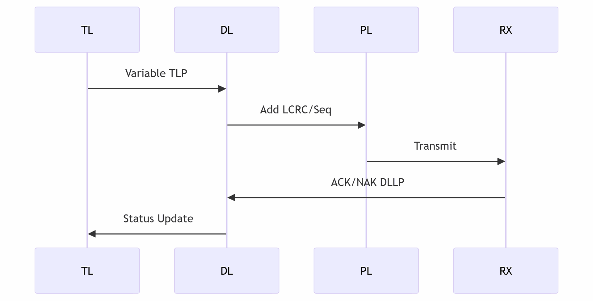
- Transmission:
- Application generates variable-size TLPs
- Data Link Layer adds sequence numbers and LCRC
- Physical Layer transmits packets
- Flow Control:
- Receiver sends credit updates via DLLPs
- Transmitter pauses if credits are exhausted
- Error Handling:
- Receiver validates LCRC
- Sends ACK/NAK DLLPs
- Entire TLP retransmitted on error
1. Non-FLIT Mode (NFM) Packet Structures (Gen1-Gen5)
A. Transaction Layer Packet (TLP) Format
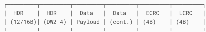
Key Fields:
- Header (12B or 16B):
- DW0: Format/Type, TC, Attributes
- DW1-3: Address/Length/Tag
- Data Payload: 0-4,096B
- ECRC: End-to-End CRC (optional)
- LCRC: Link CRC (mandatory)
B. Data Link Layer Packet (DLLP) Format
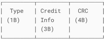
DLLP Types:
- Flow Control (FC) DLLPs:
- InitFC1/InitFC2 (buffer initialization)
- UpdateFC (credit updates)
- ACK/NAK DLLPs:
- ACK (sequence number acknowledgment)
- NAK (retransmission request)
- Power Management:
- PM_Enter_L1/PM_Enter_L23
Limitations at Higher Speeds
By PCIe 5.0 (32 GT/s), several issues emerged:
- Bandwidth Overhead
- DLLPs consumed 3-5% of total bandwidth
- Variable TLP sizes created alignment inefficiencies
- Latency Challenges
- Waiting for credit updates added unpredictable delays
- Small packets suffered disproportionate overhead
- Error Recovery
- Full TLP retransmission wasted bandwidth
- Complex buffer management requirements
Part 2: The FLIT Revolution (PCIe Gen6)
Why FLIT Mode Was Necessary
PCIe 6.0's 64 GT/s data rate demanded a more efficient protocol. FLIT mode introduced:
- Fixed 256B Packet Size
- Eliminates alignment waste
- Simplifies buffer management
- Embedded Control Information
- Flow control credits in FLIT headers
- Eliminates separate DLLPs
- Advanced Error Handling
- End-to-End CRC (ECRC)
- FLIT-level retransmission
- Forward Error Correction (FEC)
FLIT Mode Architecture
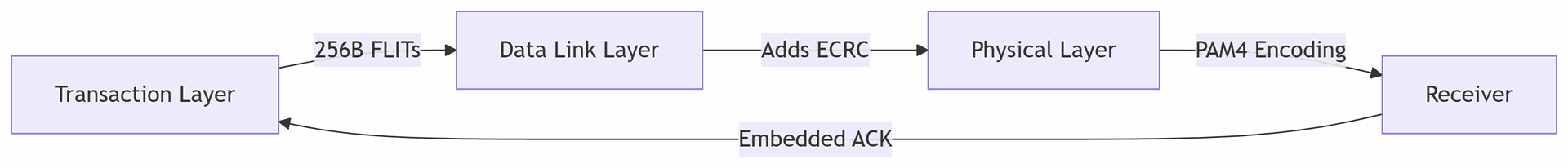
Key components:
- FLIT Structure:
- 16B header (control + credits)
- 236B payload (data + padding)
- 4B ECRC
- Flow Control:
- Credit updates in every FLIT header
- No waiting for separate DLLPs
- Error Recovery:
- FEC corrects minor errors without retransmission
- Only corrupt FLITs are resent
FLIT Mode Packet Structure (Gen6)
A. FLIT Format (256B Fixed Size)
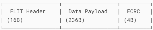
FLIT Header Details (16B):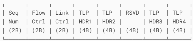
Key Components:
- Sequence Number: For error detection
- Flow Control: Replaces DLLP credits
- P/NP (Posted/Non-Posted) credits
- Cpl (Completion) credits
- Link Control: Power management states
- TLP Headers: Up to 4 embedded TLP headers
How FLIT Replaces DLLP Functions
| DLLP Function | FLIT Implementation |
|---|---|
| Flow Control Credits | Embedded in FLIT header (2B FC field) |
| ACK/NAK | Sequence numbers + ECRC |
| Power Management | Link Control field |
| Vendor Specific | Special FLIT types |
Key Differences in Packet Handling
A. Transmission Comparison
Non-FLIT Mode:
FLIT Mode: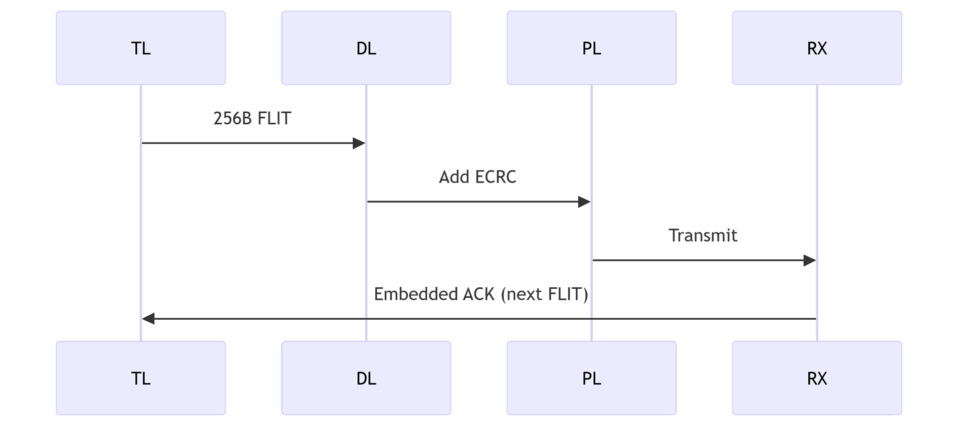
Conclusion: Why FLIT Mode Matters
The transition to FLIT mode represents a fundamental shift in PCIe's design philosophy:
- From Variable to Fixed
- Predictable performance replaces best-effort delivery
- From Distributed to Integrated
- Control functions merge into data packets
- From Reactive to Proactive
- FEC prevents errors before they occur
For system designers, this means:
- Easier performance tuning
- More consistent quality of service
- Better scaling to extreme data rates
