The Ordering and Receive Buffer Flow Control mechanism in PCI Express (PCIe) is fundamental to ensuring efficient and error-free communication between connected devices. This mechanism prevents buffer overflows, maintains compliance with ordering rules, and manages data flow across a link. This article details the concepts, rules, and implementation considerations as outlined in the PCIe Base Specification.
Purpose and Overview of Flow Control
Flow Control (FC) ensures:
- Prevention of Buffer Overflow: Prevents the receiver’s buffers from being overwhelmed by transmitted data.
- Ordering Compliance: Enables compliance with the ordering rules .
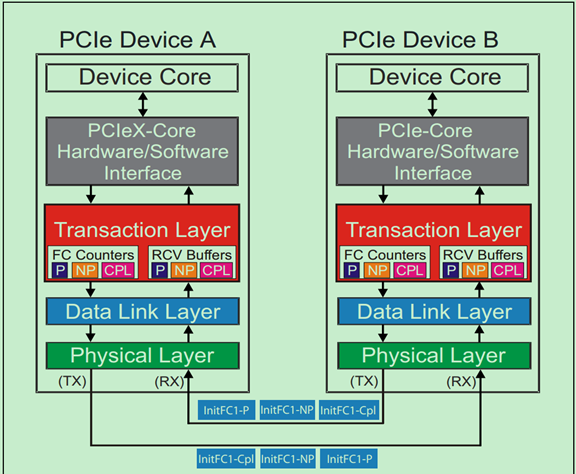
Flow Control operates on a point-to-point basis across a PCIe link rather than end-to-end. This means the mechanism tracks available buffer space only between directly connected devices, not throughout the system. For example, as illustrated in the specification, the Requester interacts with intermediate components and ultimately the Completer, but Flow Control is local to each link.
Flow Control Packets (FCPs)
- What are they?
- Flow Control Packets (FCPs) are a type of Data Link Layer Packet (DLLP) used to exchange Flow Control information between devices.
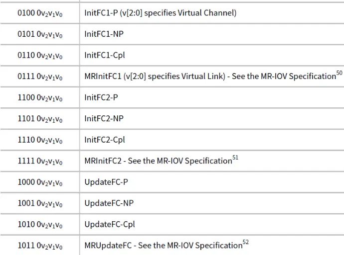
- InitFC1, InitFC2, and UpdateFC DLLPs are used for Flow Control. below is DLLP encoding type -
- Purpose:
- They help track and manage buffer space availability for different types of data and headers.
Independence from Data Integrity
Flow Control does not handle data integrity directly. Mechanisms like retransmissions ensure reliable information exchange, enabling Flow Control to assume that data transmitted between devices is error-free.
Independent Credit Pools for Virtual Channels
- Each Virtual Channel (VC) manages its own Flow Control credit pool.
- Flow Control information is transmitted between two sides of the Link via Data Link Layer Packets (DLLPs).
- The VC ID field in DLLPs identifies the VC for proper credit accounting.
- Guarantee transmitter wont send a TLP unless receiver at the other end of the link has buffer space to take it.
- Prevent buffer over-runs and eliminate inefficient transaction on the link.
Note: Flow Control mechanisms used internally within an MFD are outside the scope of this specification.
Flow Control Rules
- Flow Control ensures devices don’t send more data or headers than the receiver can handle.
- It uses Flow Control Packets (FCPs) to share buffer space availability information.
- Virtual Channels manage Flow Control independently, tracking six types of information (headers and data for posted, non-posted, and completion packets).
Units of Flow Control Credits :
- Data Credits:
- The basic unit for tracking data Flow Control is 4 Double Words (4 DW). A DW is 32 bits, so 4 DW = 128 bits or 16 bytes.
- Header Credits:
- The unit for header credits depends on whether the receiver supports TLP prefixes:
- Without TLP Prefixes:
- The credit unit includes one maximum-size header and a TLP Digest (used for error checking).
- 5 DW for Request Headers
- 4 DW for Completion Headers
- With End-to-End TLP Prefixes: If End-to-End TLP Prefixes are supported
- The credit unit includes one maximum-size header, the TLP Digest, and the maximum number of End-to-End TLP Prefixes allowed.
- With Local TLP Prefixes:
- The credit unit depends on the specific type of Local TLP Prefix used.
- Without TLP Prefixes:
- The unit for header credits depends on whether the receiver supports TLP prefixes:
- If a TLP type can't be sent due to lack of credits, other type may be sent if there are enough credits for them.
- For TLP with data ( writes and completion with data) transmitter must check both header and data credits.
Credit Types and Tracking
Flow Control tracks six types of credits, split by Transaction Layer Packet (TLP) headers and data payloads.
| Credit Type | TLP Information |
|---|---|
| PH | Posted Request Headers |
| PD | Posted Request Data Payloads |
| NPH | Non-Posted Request Headers |
| NPD | Non-Posted Request Data Payloads |
| CplH | Completion Headers |
| CplD | Completion Data Payloads |
Each VC maintains these credit types independently, enabling fine-grained control over different TLP categories.
TLP Credit Consumption
Credits are consumed whenever a TLP is transmitted. The amount of credit depends on the TLP type:
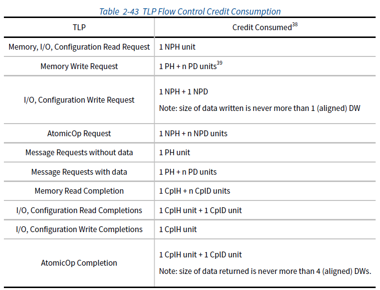
Here, n is calculated as the rounded-up length of the data payload divided by the Flow Control unit size (4 DW).
Flow Control Initialization
- VC0 initializes automatically after reset, while other VCs need software to enable them.
- Enabling or disabling a VC controls whether Flow Control tracking is active for that VC.
- Special packets (InitFC1, InitFC2) help with initialization but are ignored for disabled VCs.
- If a TLP (Transaction Layer Packet) uses a Virtual Channel (VC) that is not enabled, it is considered a Malformed TLP and will trigger an error.
- VC0 is always enabled, but VCs 1-7 must be properly configured (the VC Enable bit set, and flow control negotiation completed) before they can be used.
- TLPs cannot be transmitted using VCs 0-7 until their initialization is complete (specifically, after exiting the FC_INIT2 state). The software needs to make sure that the VC negotiation has been finalized before using any VC.
Flow Control for Default Virtual Channel (VC0)
- Every PCIe component must handle Flow Control for all Virtual Channels it supports.
- The default Virtual Channel (VC0) is automatically initialized by the hardware when:
- The Data Link Layer enters the DL_Init state (this happens after a reset).
Flow Control for Other Virtual Channels
- Virtual Channels other than VC0 (like VC1, VC2, etc.) are enabled by software:
- Software turns on a VC by setting the VC Enable bits in the VC Resource Control registers in both devices on the link.
- Each enabled VC starts the Flow Control initialization protocol independently.
- Multiple VCs can initialize simultaneously, each following its own process.
- The Flow Control initialization protocol uses InitFC1 and InitFC2 DLLPs to exchange initial credit values.
Disabling Virtual Channels
- A Virtual Channel can be disabled by software:
- This is done by clearing the VC Enable bits in the VC Resource Control registers in both devices on the link.
- When disabled, the Flow Control mechanism for that VC is reset. - Disabling a VC resets its Flow Control mechanism, clearing all credits for that channel.
Flow Control Packets (FCPs) for Initialization
- InitFC1 and InitFC2 are special Flow Control Packets (FCPs) used during initialization.
- If any of these packets (InitFC1, InitFC2, or UpdateFC) reference a disabled Virtual Channel, they are simply ignored.
Credit Advertisement
- Initial Credit Advertisement
- During initialization, devices (receivers) must announce the minimum buffer space (credits) they have for each Virtual Channel (VC). These values depend on whether Scaled Flow Control is active.
- No Scaling or Scale Factor 1: Default minimum values are used.
- With Scale Factors (4 or 16): Credits are adjusted based on scaling.
- During initialization, devices (receivers) must announce the minimum buffer space (credits) they have for each Virtual Channel (VC). These values depend on whether Scaled Flow Control is active.
- Credit Types and Minimum Values
Devices advertise initial credits for each type of data:
- PH (Posted Headers): At least 1 unit (or more, based on scaling).
- PD (Posted Data): Depends on the largest payload size the device supports.
- NPH (Non-Posted Headers): At least 1 unit.
- NPD (Non-Posted Data):
- Devices handling Atomic Operations need more credits.
- CplH (Completion Headers):
- If peer-to-peer traffic is supported: finite credits (e.g., 1 unit with Scale Factor 1).
- If no peer-to-peer traffic: infinite credits (interpreted as "no limit").
- CplD (Completion Data): Similar to PD, adjusted for scaling.
- Infinite Credits
- If a device advertises infinite credits (value 0), it tells the transmitter to send without limits for that type of data/header.
- For infinite credits, no Flow Control updates are needed, but if updates are sent, their values should be ignored.
- Flow Control Initialization Rules
- VC0 (Default VC): Automatically initialized by hardware during link setup.
- VC1–VC7 (Additional VCs):
- Enabled by software via the VC Enable bits.
- Each VC follows an independent initialization process using special packets (InitFC1, InitFC2).
- A Virtual Channel can only be used after its initialization is complete (FC_INIT1 → FC_INIT2 state).
- Disabling Virtual Channels
- Software can disable a VC by clearing its VC Enable bits, which resets its Flow Control system.
- Errors and Protocol Rules
- If a Transmitter violates Flow Control rules (e.g., exceeds available credits or mismatches scaling factors), it results in a Flow Control Protocol Error (FCPE).
- Transmitting TLPs for a disabled VC is treated as a Malformed TLP, causing an error.
| Credit Type | Description | Scale Factor 1 (No Scaling) | Scale Factor 4 | Scale Factor 16 |
|---|---|---|---|---|
| PH (Posted Headers) | Buffer space for headers of Posted Requests (e.g., memory writes, messages). | 1 unit (value 01h). | 4 units (value 01h). | 16 units (value 01h). |
| PD (Posted Data) | Buffer space for Posted Data payloads (e.g., data in memory writes). | Calculated as the maximum payload size divided by 16 (FC unit size). Example: For a 1024-byte payload, the minimum is 040h. | Calculated as the maximum payload size divided by 64 + 1. Example: 011h. | Calculated as the maximum payload size divided by 256 + 1. Example: 005h. |
| NPH (Non-Posted Headers) | Buffer space for headers of Non-Posted Requests (e.g., memory reads, configuration writes). | 1 unit (value 01h). | 4 units (value 01h). | 16 units (value 01h). |
| NPD (Non-Posted Data) | Buffer space for Non-Posted Data payloads (e.g., data in AtomicOps). | - Receivers supporting AtomicOp: 2 units (002h). - Other receivers: 1 unit (001h). | - AtomicOp: 8 units (002h). - Others: 4 units (001h). | - AtomicOp: 32 units (002h). - Others: 16 units (001h). |
| CplH (Completion Headers) | Buffer space for headers of Completion TLPs (responses to Non-Posted Requests). | - Root Complex supporting peer-to-peer traffic: 1 unit (01h). - Otherwise: Infinite credits (interpreted as all 0s). | - Peer-to-peer: 4 units (01h). - Otherwise: Infinite credits (all 0s). | - Peer-to-peer: 16 units (01h). - Otherwise: Infinite credits (all 0s). |
| CplD (Completion Data) | Buffer space for data in Completion TLPs. | For peer-to-peer traffic: The largest payload size divided by 16 (FC unit size). | For peer-to-peer traffic: Largest payload size divided by 64 + 1. | For peer-to-peer traffic: Largest payload size divided by 256 + 1. |
- Scaling Factors Adjust Credit Units:
- No Scaling (Scale Factor 1): Default credit values.
- Scale Factor 4 and 16: Reduce the number of credits needed for larger payload sizes, allowing more efficient resource utilization.
- Infinite Credits for Specific Cases:
- If a Root Complex or Endpoint does not handle peer-to-peer traffic, it advertises infinite credits for Completion Headers (CplH) and Completion Data (CplD). Infinite credits are represented by an all-zero value.
- Special Case for Atomic Operations:
- Receivers supporting AtomicOp routing or completion require more credits for Non-Posted Data (NPD) compared to regular operations.
- Posted Data (PD) and Completion Data (CplD):
- Minimum credit values depend on the maximum payload size supported by the receiver.
- Example: For a 1024-byte payload:
- Scale Factor 1: 1024 ÷ 16 = 64 credits (040h).
- Scale Factor 4: 1024 ÷ 64 + 1 = 17 credits (011h).
- Scale Factor 16: 1024 ÷ 256 + 1 = 5 credits (005h).
It ensures that:
- Transmitters have clear limits on how much data they can send.
- Receivers can handle the advertised data without buffer overflows.
- The scaling factors allow flexibility and efficiency in resource management.
- credits represent buffer space, and devices must ensure their advertisements match their actual capabilities.
- Initialization ensures smooth data flow by establishing how much data can be sent without overwhelming the receiver.
- Infinite credits simplify Flow Control by removing restrictions for specific data types.
Root Complex and Completion Credits:
- If the Root Complex (RC) does not allow peer-to-peer traffic between its Root Ports, it must advertise infinite completion credits on all Root Ports. This means that no traffic will be blocked due to lack of credits.
- If the RC allows peer-to-peer traffic, it can advertise finite completion credits on some or all Root Ports, but it must ensure that no deadlocks happen, and that the system can keep progressing, even if there's a temporary credit shortage.
Receiver Flow Control:
- A Receiver that does not support scaled flow control must ensure that it does not give more than a certain number of unused credits for data or header to the Transmitter (2047 for data, 127 for header).
- If scaled flow control is supported, the Receiver must not give more credits than the specified maximum values .
Flow Control Violations:
- Components may check for violations of the flow control rules. If a violation is detected, it is considered a Flow Control Protocol Error (FCPE), and the error is reported to the receiving port.
Infinite Credit Advertisement:
- If the RC advertises infinite credits during initialization (i.e., a value of 00h or 000h), there are no updates needed for flow control after initialization.
- If updates are sent, the credit fields should be cleared and ignored by the receiver, and any violation of this rule will trigger an FCPE.
Flow Control Updates with Infinite Credits:
- If only data or header credits (but not both) are advertised as infinite during initialization, the updates for the non-infinite part must still be sent, but the infinite part should be set to zero and ignored by the Receiver. Violations of this rule will also lead to FCPE.
Scaled Flow Control:
- If Scaled Flow Control is enabled, the HdrScale and DataScale values in flow control updates must match the values advertised during initialization. Any mismatch will trigger an FCPE.
Why Scaled Flow Control is Needed:
- At higher link speeds (e.g., 16.0 GT/s), there is a concern that insufficient flow control credits could negatively impact performance. Flow control credits are used to ensure that data is transmitted without overwhelming the receiver.
- Header credits: Control credits related to header data.
- Data credits: Control credits related to actual data payload.
- Link round-trip time: The time it takes for data to travel from the sender to the receiver and back. If there are not enough credits to account for this round-trip time, the link's performance could degrade.
Scaled Flow Control Mechanism:
- The Scaled Flow Control mechanism was introduced to overcome the credit limitations and improve performance. This mechanism is required for links operating at 16.0 GT/s and higher data rates.
- When Scaled Flow Control is NOT Activated:
- Initialization and Update DLLPs (Data Link Layer Packets) must have the HdrScale and DataScale fields set to 00b, indicating that Scaled Flow Control is not in use.
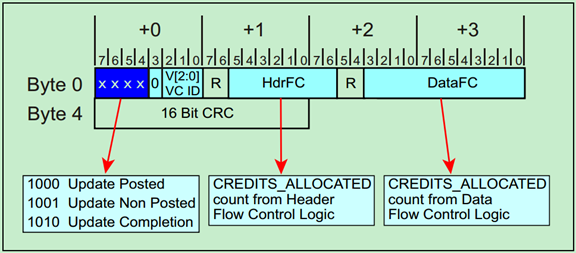
- The HdrFC counter (for header credits) is 8 bits wide, and the DataFC counter (for data credits) is 12 bits wide.
- HdrFC DLLP: Transmits the header flow control count (8 bits).
- DataFC DLLP: Transmits the data flow control count (12 bits).
- When Scaled Flow Control is Activated:
- Initialization DLLPs (InitFC1 and InitFC2) contain HdrScale and DataScale fields set to 01b, 10b, or 11b, depending on the maximum number of credits that will be outstanding.
- HdrScale and DataScale values determine the scaling factors for the credits.
- For example, 01b might represent 1-127 credits, 10b might represent 4-508 credits, and 11b could represent 16-2,032 credits.
- After receiving the HdrScale and DataScale values during initialization (in state FC_INIT1), if the values are non-zero, Scaled Flow Control is enabled on that virtual channel (VC), and UpdateFC DLLPs must reflect these scale values.
- If the values in FC_INIT1 are zero, Scaled Flow Control is not activated, and UpdateFC DLLPs must use 00b for both HdrScale and DataScale.
- Scaled Flow Control Scaling Factors :
| Scale Factor | Scaled Flow Control Support -ed | Credit Type | Min Credits | Max Credits | Field Width | FC DLLP Field Trans- mitted | FC DLLP Field Received |
|---|---|---|---|---|---|---|---|
| 00b | No | Hdr | 1 | 127 | 8 bits | HdrFC | HdrFC |
| Data | 1 | 2,047 | 12 bits | DataFC | DataFC | ||
| 01b | Yes | Hdr | 1 | 127 | 8 bits | HdrFC | HdrFC |
| Data | 1 | 2,047 | 12 bits | DataFC | DataFC | ||
| 10b | Yes | Hdr | 4 | 508 | 10 bits | HdrFC >> 2 | HdrFC << 2 |
| Data | 4 | 8,188 | 14 bits | DataFC >> 2 | DataFC << 2 | ||
| 11b | Yes | Hdr | 16 | 2,032 | 12 bits | HdrFC >> 4 | HdrFC << 4 |
| Data | 16 | 32,752 | 16 bits | DataFC >> 4 | DataFC << 4 |
- The table shows how the scaling factors (00b, 01b, 10b, 11b) influence the credit range for headers and data:
- 00b (No Scaled Flow Control):
- Header: 1 to 127 credits
- Data: 1 to 2,047 credits
- The credit fields are 8 bits for header and 12 bits for data.
- 01b (Scaled Flow Control Supported):
- Same credit ranges as 00b, but Scaled Flow Control is enabled.
- 10b (Scaled Flow Control Supported):
- Header: 4 to 508 credits
- Data: 4 to 8,188 credits
- Credit fields are wider (10 bits for header and 14 bits for data).
- 11b (Scaled Flow Control Supported):
- Header: 16 to 2,032 credits
- Data: 16 to 32,752 credits
- Credit fields are 12 bits for header and 16 bits for data.
- 00b (No Scaled Flow Control):
- Impact of Scaling:
- Scaled Flow Control enables a larger range of credits, allowing for more efficient flow control, especially at higher data rates. It adjusts the available credit range dynamically based on the system's needs, improving performance at higher link speeds.
- Summary:
- Scaled Flow Control is crucial for high-speed links (16.0 GT/s and higher) to prevent performance bottlenecks caused by insufficient flow control credits.
- It allows for greater flexibility in managing header and data credits, and it is activated via specific values in the HdrScale and DataScale fields during initialization.
- The credit ranges vary depending on the scale factor, with the ability to adjust credits as needed for efficient data transmission without overloading the receiver.
- In short, Scaled Flow Control improves the handling of flow control credits, which is especially important for maintaining high performance in high-speed PCIe links.
Key Rules for Flow Control
TLP Transmission Rules
- Credits Required: A TLP cannot be transmitted unless sufficient credits are available for its type and size.
- Gatekeeper Function: The Transaction Layer acts as a gatekeeper, ensuring TLPs pass only when credits are sufficient.
Error Handling
- Malformed TLPs: A received TLP for a disabled VC is considered malformed.
- Flow Control Protocol Errors (FCPEs): Violations of scaling or credit limits result in FCPEs, which are reported as errors.
Infinite Credit Mode
- Some components may advertise infinite credits (value of 0) during initialization. In this case, Flow Control updates are not required.
Practical Example of Flow Control
Initialization
- Device A advertises 4 PH credits, 16 PD credits, and 2 CplH credits to Device B during initialization.
- These values are exchanged using InitFC1/InitFC2 DLLPs.
Transmission
- Device A sends a Memory Write (1 PH, 8 PD).
- Device B decrements its PH and PD credit pools by 1 and 8, respectively.
- Device B processes the TLP and sends an UpdateFC DLLP to replenish its credit pool.
Counter Rollover
Flow control counters have a fixed width, such as:
- Header FC counter: 8 bits (0–255).
- Data FC counter: 12 bits (0–4095).
When a counter reaches its maximum value, it resets to zero. This process is known as a rollover. For instance:
- If an 8-bit counter reaches 255 and increments, it rolls over to 0.
Maintaining synchronization between the transmitter and receiver during rollover is critical for reliable data flow.
How Does Counter Rollover Work?
Initialization Phase
- At the start of communication, the receiver advertises the initial number of credits available using InitFC DLLPs.
- The transmitter initializes its flow control counters accordingly.
Data Transmission Phase
- As the transmitter sends TLPs, it decrements its local credit counters for the corresponding header and data resources.
- The receiver processes the incoming packets and replenishes its buffer space.
UpdateFC DLLPs
- The receiver sends periodic UpdateFC DLLPs to inform the transmitter of available credits.
- These DLLPs include the current values of the HdrFC and DataFC counters.
Rollover Handling
When the counter rolls over:
- The receiver continues to update its counters and sends the new (rolled-over) values in UpdateFC DLLPs.
- The transmitter uses modulo arithmetic to interpret the rollover and calculate the correct number of credits.
Example of Counter Rollover
Scenario
- The HdrFC counter is 8 bits, with a range of 0–255.
- The transmitter initially has 240 credits.
- The receiver processes packets and sends an UpdateFC DLLP, indicating the counter is now 10 (after rollover).
Transmitter Interpretation
To determine the credits added:
New Available Credits=(New Counter Value−Previous Counter Value+Max Counter Value+1)mod(Max Counter Value+1)
Substituting the values:
New Available Credits for Header=(10−240+256)mod 256 = 26
Thus, the transmitter understands that 26 new credits are available.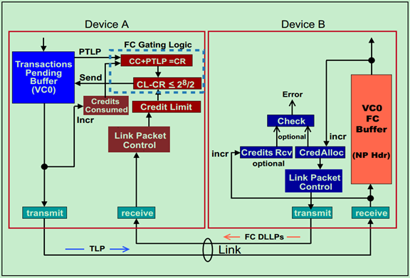
For Header credit check,
CreditLimit-(CreditConsumed + PendingTLP)mod 256<= 128
For Data credit check,
CreditLimit-(CreditConsumed + PendingTLP)mod 4096<= 2048
Synchronization
The transmitter continues sending packets without disruption, as the modulo arithmetic ensures seamless credit tracking.
Benefits of Rollover Mechanism
- Efficiency: Counters of limited width save bandwidth while ensuring precise tracking.
- Scalability: The mechanism adapts to high data rates and large credit limits.
- Robustness: Modulo arithmetic ensures accurate credit calculations, even during rollovers.
Rollover Process
Steps involved:
- Initialization: Counters are set, and initial credits are advertised.
- Transmission: Transmitter decrements credits as packets are sent.
- UpdateFC DLLPs: Receiver replenishes credits and sends counter updates.
- Rollover: Counter resets, and modulo arithmetic ensures proper credit calculations.
DL_Feature and Data Link Feature Extended Capability
DL_Feature: Data Link Feature Exchange
The Data Link Feature Exchange is a protocol introduced to negotiate and share supported features between two interconnected PCIe ports. This process ensures compatibility and enables advanced functionality, particularly in high-speed configurations.

Key Components of Data Link Feature Exchange
-
Protocol Overview:
- The exchange uses Data Link Layer Packets (DLLPs) to communicate feature support between ports.
- Negotiation ensures that only compatible features are enabled, avoiding operational conflicts.
-
Operational Flow:
- Protocol Activation: When the DL_Feature state is entered, the system resets fields like Remote Data Link Feature Supported and Remote Data Link Feature Supported Valid, initializing the negotiation process.
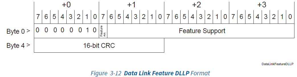
- Feature Exchange: DLLPs are transmitted every 34 microseconds, carrying feature data. The Feature Ack bit confirms the validity of received feature settings.
- Completion: The protocol concludes once both ports acknowledge the features or upon detection of reset/initialization DLLPs such as InitFC1.
-
Supported Features:
- Scaled Flow Control is a critical feature negotiated during the exchange. It dynamically adjusts buffer management for high-speed links, ensuring efficient operation at 16 GT/s and above.
Comparison: Gen3 vs Gen5
| Aspect | PCIe Gen3 | PCIe Gen5 |
|---|---|---|
| Supported Speed | Up to 8 GT/s | Up to 32 GT/s |
| Mandatory Feature Exchange | Not required | Required for downstream ports at 16 GT/s or higher |
| DLLP Interval | N/A | DLLPs transmitted every 34 microseconds |
| Feature Support | Limited | Includes Scaled Flow Control for high-speed links |
Advantages in Gen5
- Ensures compatibility and feature negotiation for high-speed links.
- Facilitates dynamic feature adjustments, reducing operational overhead.
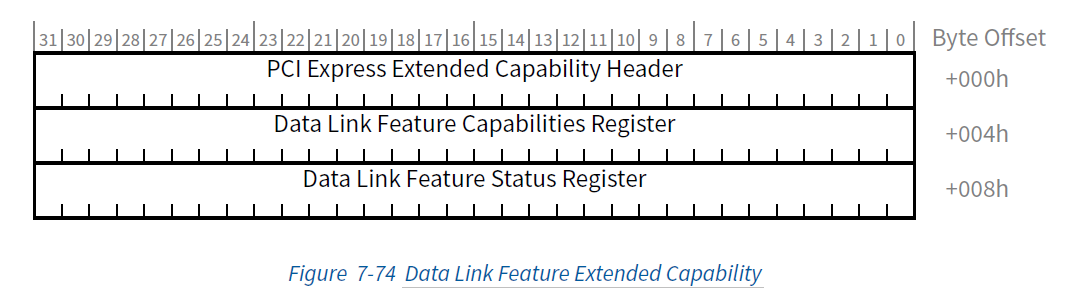
Data Link Feature Extended Capability
The Data Link Feature Capability is an optional extended capability designed to support advanced features, such as Scaled Flow Control.
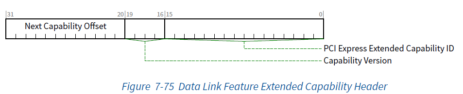
- Capability ID: Identifies the extended capability as 0025h (specific to Data Link Feature Extended Capability).
- Capability Version: Indicates the version of the capability structure. For this, the version is likely 1h.
- Next Capability Offset: Points to the next extended capability in the PCIe configuration space.
The header establishes the basis for identifying and chaining capabilities in a PCIe device.
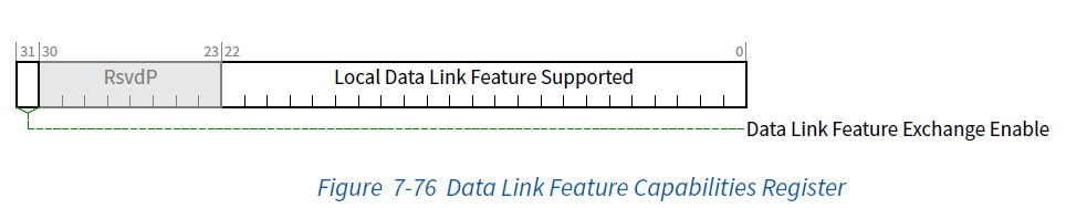
This register specifies the local capabilities of the port. Key fields include:
- Local Scaled Flow Control Support: Indicates whether the port supports Scaled Flow Control, critical for high-speed (16 GT/s and above) operations.
- Data Link Feature Exchange Enable: Controls whether the exchange of Data Link Layer features is enabled. The default value is typically 1b (enabled).
- Reserved Fields: Reserved for future use and should be set to zero by default.
This register is crucial for negotiating supported features during the Data Link Layer initialization.
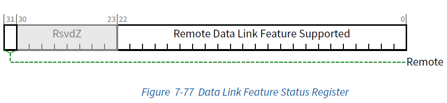
This register tracks the status of features supported by the remote port. Key fields include:
- Remote Scaled Flow Control Support: Reflects whether the connected port supports Scaled Flow Control, as advertised during the negotiation.
- Remote Data Link Feature Valid: Indicates whether the received remote capabilities are valid.
- Reserved Fields: Reserved for future use.
This status register is dynamically updated based on the DLLPs (Data Link Layer Packets) exchanged between ports
The following highlights key aspects:
Applicability
- Mandatory for Downstream Ports: Required for Downstream Ports supporting speeds of 16 GT/s or higher. The presence of the Scaled Flow Control feature necessitates this requirement.
- Optional for Other Configurations: This capability is optional for:
- Downstream Ports operating at lower speeds.
- Functions associated with an Upstream Port.
- Multi-function Devices: For multi-function devices, all instances of this capability must report identical data across functions.
- Not Applicable: This capability does not apply to non-port-associated functions (e.g., Root Complex Integrated Endpoints).
Structure Overview
The Data Link Feature Extended Capability includes the following components:
-
PCI Express Extended Capability Header (Offset 00h):
- Identified by Extended Capability ID = 0025h.
- Capability Version must be 1h.
- Contains a pointer to the next capability in the linked list or terminates with 000h.
-
Data Link Feature Capabilities Register (Offset 04h):
- Tracks locally supported features. These features are transmitted to the remote port during negotiation.
- Includes:
- Local Scaled Flow Control Support: Indicates whether Scaled Flow Control is supported.
- Data Link Feature Exchange Enable: Determines whether the exchange protocol is active (default 1b).
-
Data Link Feature Status Register (Offset 08h):
- Tracks features supported by the remote port.
- Captures the received Scaled Flow Control and feature exchange state.
Comparison with PCIe Gen3
| Aspect | PCIe Gen3 | PCIe Gen5 |
|---|---|---|
| Data Link Feature Extended Capability | Not defined | Mandatory for Downstream Ports (16 GT/s+) |
| Feature Negotiation | Limited | Includes Scaled Flow Control |
| Multi-function Support | Not applicable | Consistency required across all functions |
Key Registers
| Register | Description |
|---|---|
| Extended Capability Header | Identifies the capability, version, and next capability offset. |
| Capabilities Register | Tracks features supported locally, including Scaled Flow Control and Exchange Enable flags. |
| Status Register | Monitors remote port features based on the Data Link Feature DLLPs received during negotiation. |
Key Rules
- Initialization:
- Reset relevant fields, including Remote Data Link Feature Supported and Valid Bit, on entering the negotiation state.
- Feature Negotiation:
- DLLPs transmit supported features every 34 microseconds.
- Negotiation concludes upon acknowledgment from the remote port.
Benefits of Flow Control
- Buffer Overflow Protection: Ensures transmitters do not overwhelm receiver buffers.
- Efficient Resource Usage: Credits enable fine-grained tracking of resource availability.
- Compliance with Ordering Rules: Preserves correctness in multi-transaction scenarios.
Conclusion
PCIe's Flow Control mechanism is a robust framework for managing the flow of data across links, balancing efficiency and correctness. By independently tracking credits for multiple Virtual Channels, devices maintain seamless communication while adhering to strict ordering rules. These capabilities make Flow Control a cornerstone of PCIe's reliability and scalability.
