Quality of Service (QoS) in PCIe
QoS in PCIe is primarily achieved through mechanisms that allow prioritization and segregation of data flows. PCIe utilizes Traffic Classes (TCs), Virtual Channels (VCs), and arbitration mechanisms to implement QoS effectively.
Key Features Enabling QoS
- Traffic Classes (TCs): Logical labels (0–7) assigned to packets to prioritize their importance. Each TC represents a specific priority level, with TC0 being the default for maintenance-level traffic.
- Virtual Channels (VCs): Separate hardware buffers acting as distinct data paths for different TCs or groups of TCs. These ensure that high-priority traffic is not delayed by lower-priority data.
- Port Arbitration: Determines how packets from different TCs are scheduled for transmission over the PCIe link. Various arbitration schemes ensure fairness and priority handling.
- Virtual Channel Arbitration: Decides the transmission order within a VC, ensuring efficient flow and minimal contention. follow this link :- Virtual Channel Arbitration Schemes
PCIe Traffic Classes (TCs)
Traffic Classes are a fundamental part of PCIe’s QoS mechanisms, allowing prioritization of data transfers across the link. Here’s a detailed breakdown:
Definition:
- Traffic Classes are represented as a 3-bit field in the Transaction Layer Packet (TLP) header.
- There are eight possible TCs, numbered from 0 to 7, where TC0 is the default and TC7 has the highest priority.
Purpose:
- To distinguish packets by their priority levels and ensure that high-priority data gets processed first.
- Helps manage mixed workloads, such as real-time video streams and bulk data transfers, over the same PCIe link.
Operation:
- A device assigns a TC value to each outgoing packet based on its importance and QoS requirements.
- The TC value remains unchanged as the packet traverses the PCIe topology.
Traffic Flow:
- Each TC is mapped to a specific Virtual Channel (VC) using a TC/VC mapping table during initialization.
- This mapping ensures that packets are segregated into appropriate channels to avoid contention between high- and low-priority traffic.
Applications:
- TC0: Default for maintenance-level traffic such as configuration and management commands.
- Higher TCs: Used for latency-sensitive and high-bandwidth applications, such as:
- Real-time audio and video streaming (e.g., TC6 or TC7).
- Storage and data center operations (e.g., TC4 or TC5).
QoS Policies:
- TCs enable differentiated services where devices and switches prioritize certain types of traffic over others.
- Combined with Virtual Channel Arbitration, this ensures that critical tasks are completed on time without being blocked by lower-priority operations.
Interoperability:
- Legacy devices unaware of TCs will default to using TC0, maintaining backward compatibility.
- Advanced systems configure TC policies dynamically based on workload demands.
Error Handling:
- If a packet’s TC/VC mapping fails or the VC buffer overflows, error flags are raised, ensuring robust QoS management.
Virtual Channels in PCIe
Virtual Channels (VCs) are critical to the implementation of QoS in PCIe, enabling the separation of traffic into independent paths based on priority levels. Here’s a detailed explanation:
Definition:
- VCs are hardware-implemented buffers or queues that segregate traffic within a PCIe link.
- Each VC corresponds to one or more Traffic Classes (TCs), creating a pathway for prioritized data flow.
Purpose:
- To prevent high-priority traffic from being delayed by lower-priority packets.
- To isolate critical operations, ensuring that faults in one VC do not disrupt others.
Operation:
- During initialization, a TC/VC mapping is established to link TCs with specific VCs.
- Devices with multiple VCs utilize arbitration schemes to determine the order of transmission for packets within a VC.
Configuration:
- VC structures are part of the PCIe Extended Configuration Space.
Managed via the VC Extended Capability registers:
- VC Capability Header
- Port VC Capability Registers (1 & 2)
- VC Resource Capability and Control Registers
- VC Arbitration Table.
Arbitration:
- Arbitration within VCs determines how packets from the same VC are processed.
- Schemes like Strict Priority Arbitration, Group Arbitration, and Weighted Round Robin are employed to maintain order and ensure fairness.
Buffer Management:
- Each VC is associated with dedicated flow control buffers for posted, non-posted, and completion transactions.
- Proper buffer management ensures no overflow or underflow conditions occur during transmission.
Error Isolation:
- If an error occurs in one VC, it is contained within that channel, preventing it from propagating to other VCs.
Applications:
- VCs are widely used in data centers, storage systems, and real-time multimedia applications to ensure smooth, prioritized operation of diverse workloads.
VC ID Assignment Rules:
- VC ID assignment must be unique per port. The same VC ID cannot be assigned to different VC hardware resources within the same port.
- VC ID assignment must match for the two ports on both sides of a link, ensuring identical VC configurations.
- For multi-function devices (MFDs) with an MFVC Capability structure, VC hardware resources are distinct from VC resources associated with other VC Capability structures. However, the VC ID uniqueness rule still applies to both MFVC and VC Capability structures individually.
- VC ID 0 is assigned and fixed to the default VC.
Virtual Channel Capability Structure

Structure Overview
Base Capability: Registers starting at offset 00h define general information about the VC capability.
Port-Level Configuration:
- Offset 04h to 0Ch focuses on port-level capability, status, and control.
VC-Level Configuration:
- Offset 10h and beyond provide detailed configurations for individual Virtual Channels.
Arbitration Configuration:
- Arbitration tables are provided at the end to define arbitration logic for TCs and ports.
1. Virtual Channel Extended Capability Header (Offset 00h)
This header identifies the VC Capability and provides linkage to other capabilities.
Fields:
- PCI Express Extended Capability ID [15:0]: Value 0002h or 0009h to indicate VC Capability.
- Capability Version [19:16]: Version of the structure (must be 1h).
- Next Capability Offset [31:20]: Offset to the next PCI Express Capability or 000h if none.
2. Port VC Capability Register 1 (Offset 04h)
Describes VC configuration for the associated port.
Fields:
- Extended VC Count [2:0]: Number of additional VCs supported beyond VC0. Values range from 0 to 7.
- Low Priority Extended VC Count [6:4]: VCs belonging to the low-priority group.
- Reference Clock [9:8]: Clock reference for time-based WRR arbitration (e.g., 00b for 100 ns).
- Port Arbitration Table Entry Size [11:10]: Size of Port Arbitration table entry (e.g., 1, 2, 4, or 8 bits).
- Reserved [31:12]: Reserved for future use.
3. Port VC Capability Register 2 (Offset 08h)
Provides further configuration details for VCs.
Fields:
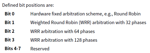
- VC Arbitration Capability [7:0]: Indicates supported arbitration schemes (e.g., Round Robin, WRR with 32, 64, or 128 phases).
- VC Arbitration Table Offset [31:24]: Offset to the VC Arbitration Table. Value 00h indicates absence.
4. Port VC Control Register (Offset 0Ch)
Controls VC arbitration and configuration updates.
Fields:
- Load VC Arbitration Table [0]: Software sets this to apply updates to the VC Arbitration Table.
- VC Arbitration Select [3:1]: Selects an arbitration scheme from the VC Arbitration Capability field in VC capability register 2.
- Reserved [31:4]: Reserved.
The VC Arbitration Capability field in the Port VC Capability Register 2 lists all supported arbitration schemes.
Each bit in this field corresponds to a specific arbitration method (e.g., Round Robin, Weighted Round Robin with varying phases).
Select a Scheme:
- The software sets the VC Arbitration Select field to a value corresponding to one of the supported schemes (indicated by the active bits in the VC Arbitration Capability field).
- For instance:
- Bit 0: Round Robin (RR)
- Bit 1: Weighted Round Robin (WRR-32 phases)
- Bit 2: Weighted Round Robin (WRR-64 phases)
Restrictions:
- Mutual Exclusivity: If multiple VCs in the Low Priority Virtual Channel (LPVC) group are enabled, the VC Arbitration Select field cannot be modified.
- This restriction ensures consistency in arbitration across enabled VCs, preventing potential conflicts or misconfigurations.
5. Port VC Status Register (Offset 0Eh)
Tracks configuration status for VCs.
Fields:
- VC Arbitration Table Status [0]: Indicates coherency of the VC Arbitration Table.
- Reserved [31:1]: Reserved for future use.
6. VC Resource Capability Register (Offset 10h + N × 0Ch)
Defines the capabilities and configurations of individual VC resources.
Fields:
- Port Arbitration Capability [7:0]: Types of supported arbitration (e.g., Round Robin, WRR).
- Maximum Time Slots [22:16]: Maximum time slots for time-based WRR arbitration.
- Port Arbitration Table Offset [31:24]: Offset to the Port Arbitration Table for the VC.
7. VC Resource Control Register (Offset 14h + N × 0Ch)
Controls individual VC resources.
Fields:
- TC/VC Map [7:0]: Maps Traffic Classes (TCs) to this VC. Bit location within this field corresponds to TC value.
Example :
suppose we want to map TC0 & TC1 to VC0 and TC2 -TC4 to VC3
then VCID for VC0 is 000b and VCID for VC3 is 011b.
Bit[7:0] for VC0 is 00000011b and for VC3 is 00011100b.
- Load Port Arbitration Table [16]: Updates Port Arbitration logic for this VC.
- Port Arbitration Select [19:17]: Configures specific arbitration services.
- VC ID [26:24]: Assigns an ID to the VC resource.
- VC Enable [31]: Enables or disables this VC.
8. VC Resource Status Register (Offset 18h + N × 0Ch)
Tracks the status of individual VC resources.
Fields:
- Port Arbitration Table Status [0]: Indicates coherency of the Port Arbitration Table for this VC.
- VC Negotiation Pending [1]: Indicates whether VC negotiation is in progress.
- Reserved [31:2]: Reserved for future use.
9. VC Arbitration Table
Located at the offset specified by the VC Arbitration Table Offset field.
- Used for WRR arbitration with a fixed entry size of 4 bits.
- Entries define arbitration phases, associating each phase with a specific VC.
Logical Flow
- Start at Capability Header [00h]: Identify the VC capability structure.
- Port-Level Details [04h–0Ch]: Configure port capabilities and status.
- VC-Level Configuration [10h onwards]:
- For each VC, configure resources, control, and monitor status.
- Arbitration Tables: Configure arbitration mechanisms using the VAT and PAT offsets.
The Virtual Channel (VC) Capability structure is crucial for managing QoS by enabling the configuration and monitoring of multiple VCs.
Components of the VC Capability Structure
- Capability Header: Identifies the type and version of VC capability and indicates the presence of VC-related features.
- Port VC Arbitration Table Offset: Specifies the memory offset where arbitration tables for managing VC traffic are stored.
- VC Resource Control Registers: Enable configuration of each VC, defining parameters like bandwidth allocation, TC/VC mapping, and priority levels.
- VC Arbitration Table: Contains information for prioritizing traffic within a VC, supporting schemes like strict priority and weighted round-robin.
- VC Resource Status Registers: Provide real-time status of each VC, including active state and error reporting.
- VC Negotiation: Ensures agreement between devices on the number and configuration of VCs for optimal operation.
Traffic Class (TC) and VC Mapping
- Mapping Mechanism: During initialization, each TC is mapped to a specific VC. For example, TC0 is always mapped to VC0.
- Consistency Across Ports: Mapping must be identical for both ends of the same link to ensure seamless traffic flow.
- No Overlap: A single TC cannot be mapped to multiple VCs to avoid conflicts in data routing.
Key Functions of VC Capability
- Bandwidth Allocation: Ensures sufficient bandwidth for critical traffic classes, preventing delays in high-priority tasks.
- Latency Management: Reduces contention by isolating high-priority traffic into dedicated VCs, ensuring predictable timing.
- Error Isolation: Errors within one VC do not affect other VCs, enhancing system reliability and fault tolerance.
Transaction Types in PCIe
PCIe transactions can be categorized based on timing requirements:
Asynchronous Transactions
- Do not have strict timing requirements and can utilize bandwidth opportunistically.
- Examples include background data transfers and general file I/O operations.
Isochronous Transactions
- Require consistent, predictable timing for latency-sensitive applications.
- Examples include:
- Real-time video streaming: Guarantees smooth playback without buffering.
- VoIP: Ensures low-latency audio communication for seamless user experience.
- Industrial control systems: Maintains precise timing for synchronized operations.
PCIe Features Supporting QoS
- Traffic Class (TC): Provides a mechanism to prioritize packets with ascending priority levels from TC0 to TC7.
- Virtual Channels (VC): Separate queues for outgoing packets ensure no interference between high- and low-priority data.
- Port Arbitration: Schedules packets from various TCs for transmission, balancing fairness and priority.
- Virtual Channel Arbitration: Manages the order of packet transmission within each VC, ensuring optimal flow control.
Flow ::
Capability Discovery:
- Start with the VC Capability Header to identify if the device supports Virtual Channels.
- Navigate to Port VC Capability Registers to determine the number of supported VCs and arbitration mechanisms.
Resource Allocation:
- Use VC Resource Capability Register to understand the buffer sizes and TC/VC mapping.
- Configure the VC Resource Control Register to enable and initialize specific VCs.
Arbitration Configuration:
- Access the VC Arbitration Table to configure priority levels and weights for Traffic Classes.
- Adjust the Port Arbitration Table (from Port VC Capability Register) to manage arbitration across ports.
Status Monitoring:
- Use the VC Resource Status Register to monitor activity, buffer utilization, and errors.
Multi-Function Devices:
- Check the MFVC Capability and Resource Registers for multi-function-specific configurations.
Error Handling:
- Review error flags in the VC Resource Status Register for troubleshooting and performance optimization.
Conclusion
Quality of Service in PCIe is a cornerstone for supporting high-performance and real-time applications. By leveraging features like Traffic Classes, Virtual Channels, and robust arbitration mechanisms, PCIe ensures prioritized handling of data flows, meeting the demands of latency-sensitive tasks such as video conferencing and industrial automation. As technology advances, these QoS mechanisms will play an even more significant role in enabling next-generation innovation.
