PCI Express (PCIe) is the backbone of high-speed data transfer in modern computing, connecting CPUs to GPUs, SSDs, and other critical components. With each new generation, PCIe doubles its bandwidth while improving efficiency and reliability.
This guide explores the key differences between PCIe Gen 4, Gen 5, Gen 6, and Gen 7, covering:
✔ Throughput calculations
✔ Signaling changes (NRZ vs PAM-4)
✔ FLIT mode in Gen 6/7
✔ Why PAM-4 replaced NRZ
✔ Real-world performance impact
1. PCIe Generations at a Glance
| Feature | PCIe Gen 4 | PCIe Gen 5 | PCIe Gen 6 | PCIe Gen 7 |
|---|---|---|---|---|
| Year Released | 2017 | 2019 | 2022 | 2025 (Planned) |
| Signaling | NRZ (2-level) | NRZ (2-level) | PAM-4 (4-level) | PAM-4 (4-level) |
| Encoding | 128b/130b | 128b/130b | FLIT (242B/256B) | FLIT (242B/256B) |
| Transfer Rate (GT/s) | 16 GT/s | 32 GT/s | 64 GT/s (32 GBd) | 128 GT/s (64 GBd) |
| Bits per Symbol | 1 bit | 1 bit | 2 bits | 2 bits |
| x16 Bandwidth | 32 GB/s | 64 GB/s | 242 GB/s | 484 GB/s |
| Error Correction | None | None | FEC (Forward Error Correction) | Enhanced FEC |
2. Throughput Comparison (Calculated Bandwidth)
Bandwidth Formula
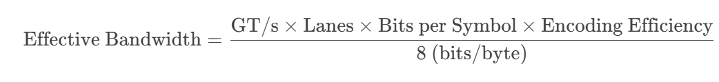
Breaking Down the Formula:
- GT/s (GigaTransfers per second)
- Raw signaling rate (e.g., 16 GT/s for Gen 4, 64 GT/s for Gen 6).
- Lanes (x1, x4, x8, x16)
- Number of parallel data lanes (x16 is common for GPUs).
- Bits per Symbol
- NRZ (Gen 1-5): 1 bit/symbol (2 voltage levels).
- PAM-4 (Gen 6+): 2 bits/symbol (4 voltage levels).
- Encoding Efficiency
- Gen 4/5 (128b/130b): 128/130 ≈ 98.46% efficiency.
- Gen 6/7 (FLIT mode): 242/256 ≈ 94.53% efficiency (due to FEC & CRC overhead).
- Divide by 8
- Converts bits to bytes (since 1 byte = 8 bits).
Throughput Calculation Formula
PCIe throughput is calculated as:
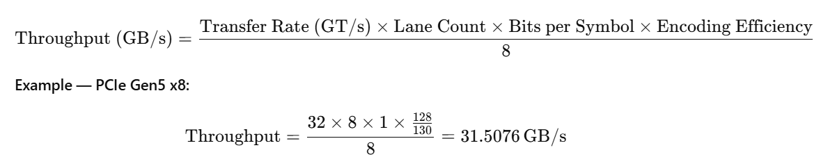
For PAM-4 (Gen6+), Bits per Symbol = 2, but FLIT structure + FEC reduce usable throughput.
PCIe Gen 4 (NRZ, 128b/130b)
- Per Lane: 1.969 GB/s
- x16 Bandwidth: 31.507 GB/s
PCIe Gen 5 (NRZ, 128b/130b)
- Per Lane: 3.938 GB/s
- x16 Bandwidth: 63.015 GB/s
PCIe Gen 6 (PAM-4, FLIT Mode)
- Per Lane: 15.125 GB/s
- x16 Bandwidth: 242 GB/s
PCIe Gen 7 (PAM-4, FLIT Mode)
- Per Lane: 30.25 GB/s
- x16 Bandwidth: 484 GB/s
3.PCIe Gen4 → Gen7 — Detailed Working Differences
PCIe has three primary layers:
- Transaction Layer – Handles packets (TLPs), ordering, addressing.
- Data Link Layer (DLL) – Ensures reliable delivery over a link (Ack/Nak, sequence numbers).
- Physical Layer – Handles signaling, encoding, symbol transmission.
3.1. Physical Layer (PHY) Differences
Gen4 → Gen5
- Signaling: Still NRZ (Non-Return-to-Zero) — 2 voltage levels, 1 bit per symbol.
- Symbol rate doubled: 16 → 32 GT/s.
- Encoding: 128b/130b retained — ~1.54% overhead.
- Result: Throughput doubled without any change in framing or protocol.
Gen5 → Gen6
-
Signaling change: NRZ → PAM-4 (Pulse Amplitude Modulation, 4 voltage levels, 2 bits per symbol).
- Each symbol now carries 2 bits, but the symbol rate is 32 GBd (gigabaud) instead of 64 GT/s raw symbols.
- PAM-4 requires more sensitive receivers — smaller voltage margins mean higher bit error rates.
- Error correction: FEC (Forward Error Correction) mandatory.
- Framing change: 128b/130b encoding removed → replaced by FLIT (Flow Control Unit) framing with fixed 256-byte structures.
- Channel requirements: Stricter insertion loss budget; retimers often required.
Gen6 → Gen7
- PAM-4 retained but symbol rate doubled from 32 GBd to 64 GBd (effectively 128 GT/s in NRZ-equivalent terms).
- FEC optimized for lower latency while maintaining required error correction.
- Channel requirements tighten further — PCB materials must support very high frequencies; active components (retimers, redrivers) almost unavoidable for long traces.
| Feature | Gen4 | Gen5 | Gen6 | Gen7 |
|---|---|---|---|---|
| Signaling | NRZ | NRZ | PAM-4 | PAM-4 |
| Symbol Rate | 16 GT/s | 32 GT/s | 64 GT/s | 128 GT/s |
| Baud Rate | 16 GBd | 32 GBd | 32 GBd | 64 GBd |
| Encoding | 128b/130b | 128b/130b | 1b/1b | 1b/1b |
| Error Control | LCRC only | LCRC only | CRC + FEC | CRC + Faster FEC |
3.2. Data Link Layer Differences
Gen4 & Gen5
-
DLLPs (Data Link Layer Packets):
- Used for Acknowledgement (Ack), Negative Ack (Nak), flow control updates.
- Sent in-band alongside TLPs but consume bandwidth.
- Error handling: If a packet fails LCRC (Link CRC), it’s retransmitted based on DLLP Nak.
- Ack/Nak latency: Directly tied to round-trip time and DLLP transmission rate.
Gen6
-
DLLP removed entirely.
- No separate Ack/Nak packets.
- Reliability and flow control embedded inside the FLIT structure.
-
FLIT reliability:
- Every FLIT includes its own CRC.
- FEC corrects most single-bit/multi-bit errors without retransmission.
- Result: Fewer retransmits → more predictable latency at high speeds.
- Impact on implementation: Controllers no longer need DLLP queues; error logic moves into FLIT + FEC handling.
Gen7
- Same no-DLLP model as Gen6.
- FEC latency reduced — needed for 128 GT/s operation.
- Ack/Nak logic remains embedded in FLIT control fields.
| Feature | Gen4 | Gen5 | Gen6 | Gen7 |
|---|---|---|---|---|
| DLLPs | Yes | Yes | No | No |
| Ack/Nak | DLLPs | DLLPs | In-FLIT control | In-FLIT control |
| Error Detection | LCRC | LCRC | FLIT CRC | FLIT CRC |
| Error Recovery | Retransmit on Nak | Retransmit on Nak | FEC + occasional retransmit | FEC + faster recovery |
3.3. Transaction Layer Differences
Across Gen4–Gen7:
- No major functional changes — transaction layer remains backward compatible.
- Still uses TLPs for memory, I/O, configuration, and message transactions.
-
Key difference in Gen6+:
- Variable-size TLPs are segmented into fixed 256B FLITs before transmission.
- Even small TLPs are padded inside a FLIT.
- In Gen4/5, TLPs are sent as-is with variable length.
| Feature | Gen4 | Gen5 | Gen6 | Gen7 |
|---|---|---|---|---|
| Packet Format | Variable TLP | Variable TLP | TLP segmented into FLITs | Same as Gen6 |
| Backward Compatibility | Yes | Yes | Yes | Yes |
| Ordering Rules | Same | Same | Same | Same |
3.4. FLIT Mode vs Non-FLIT Mode
detailed information is available :: pcie-6
| Feature | Gen4/5 (Non-FLIT) | Gen6/7 (FLIT) |
|---|---|---|
| TLP Size | Variable (up to 4KB) | Packed into 256B units |
| Overhead | Encoding (128b/130b) + DLLPs | FLIT CRC + FEC (no DLLPs) |
| Ack/Nak | Separate DLLPs | Embedded in FLIT |
| Error Handling | Retransmission on Nak | FEC corrects most errors, minimal retransmits |
| Efficiency | Slightly better for small packets | Slightly lower for small packets (padding), better for large sustained transfers |
| Complexity | Lower PHY complexity | Higher PHY complexity (PAM-4, FEC, fixed framing) |
3.5. Summary Table — Key Working Changes
| Layer | Gen4 | Gen5 | Gen6 | Gen7 |
|---|---|---|---|---|
| Physical | 16 GT/s NRZ, 128b/130b | 32 GT/s NRZ, 128b/130b | 64 GT/s (32 GBd) PAM-4, FLIT framing | 128 GT/s (64 GBd) PAM-4, FLIT |
| Encoding | 128b/130b | 128b/130b | None (1b/1b inside FLIT) | None (1b/1b inside FLIT) |
| DLL | DLLPs, LCRC | DLLPs, LCRC | No DLLPs, CRC in FLIT, FEC added | No DLLPs, CRC in FLIT, faster FEC |
| Transaction | Variable TLP | Variable TLP | TLP segmented into FLITs | Same as Gen6 |
| Error Handling | LCRC + retransmit | LCRC + retransmit | FEC + CRC, minimal retransmit | Same but faster FEC |
Gen4 → Gen5: Same architecture, doubled GT/s.
Gen5 → Gen6: PAM-4 signaling, fixed 256B FLITs, DLLP removed, FEC added.
Gen6 → Gen7: Same architecture, doubled GT/s, faster FEC, stricter channel requirements.
4.NRZ vs PAM-4: Why the Shift Happened
Problems with NRZ (Gen 1-5)
- Bandwidth Wall
- NRZ transmits 1 bit per clock cycle (0 or 1).
- To double speeds, frequency must double, leading to signal degradation.
- Signal Integrity Issues
- At 32 GT/s (Gen 5), NRZ suffers from:
- Inter-symbol interference (ISI)
- Higher power consumption
- Strict PCB trace length requirements
- At 32 GT/s (Gen 5), NRZ suffers from:
- No Built-in Error Correction
- NRZ relies on retransmission, increasing latency.
Advantages of PAM-4 (Gen 6+)
- Double Bandwidth at Same Frequency
- PAM-4 uses 4 voltage levels (00, 01, 10, 11), encoding 2 bits per cycle.
- 64 GT/s (Gen 6) = 32 GBaud (symbol rate) × 2 bits/symbol
- Better Spectral Efficiency
- Same frequency, double data rate compared to NRZ.
- Forward Error Correction (FEC)
- Corrects errors without retransmission, reducing latency.
- Lower Power per Bit
- More efficient than pushing NRZ to extreme frequencies.
5. FLIT Mode in Gen 6 & 7: How It Works
What is FLIT Mode?
- FLIT = Flow Control Unit (fixed-size packets, 256B in PCIe Gen 6/7).
- Replaces variable-sized TLPs (Transaction Layer Packets) in Gen 1-5.
FLIT Structure (Gen 6/7)
| Field | Size | Purpose |
|---|---|---|
| Payload | 242B | Actual data |
| CRC | 8B | Error detection |
| FEC Parity | 6B | Error correction |
Benefits of FLIT Mode
✔ Fixed Packet Size → Predictable latency.
✔ No DLLPs (Data Link Layer Packets) → Reduced overhead.
✔ Better Error Handling → FEC corrects errors without retransmission.
✔ Higher Efficiency (~94.5% payload efficiency vs ~92% in Gen 5).
Where is FLIT Used?
- AI/ML Workloads (NVIDIA, AMD GPUs)
- High-Performance SSDs (PCIe 6.0 NVMe)
- Data Center & Hyperscale Computing
6. Real-World Performance Impact
| Use Case | Gen 4 (2017) | Gen 5 (2019) | Gen 6 (2022) | Gen 7 (2025) |
|---|---|---|---|---|
| Gaming GPUs | ✅ (No bottleneck) | ✅ (Future-proof) | ❌ (Overkill) | ❌ (Enterprise) |
| NVMe SSDs | ~7 GB/s (x4) | ~14 GB/s (x4) | ~30 GB/s (x4) | ~60 GB/s (x4) |
| AI/ML Acceleration | ❌ (Limited) | ⚠ (Moderate) | ✅ (Optimal) | ✅ (Best) |
| Data Centers | ❌ (Outdated) | ⚠ (Limited) | ✅ (Adopted) | ✅ (Next-gen) |
7. Conclusion: Which PCIe Gen Should You Use?
| Generation | Best For | Limitations |
|---|---|---|
| Gen 4 | Mainstream gaming, consumer SSDs | Maxes out at 32 GB/s (x16) |
| Gen 5 | High-end GPUs, enterprise SSDs | Signal integrity challenges |
| Gen 6 | AI, HPC, data centers | Requires PAM-4 & FLIT support |
| Gen 7 | Future AI/ML, quantum computing | Early adoption, high cost |
Final Verdict
- Gamers & General Users: Gen 4/5 are sufficient.
- Professionals (AI, Data Science): Gen 6 is ideal.
- Enterprise/Cloud: Gen 7 will dominate in 2025+.
The shift from NRZ → PAM-4 and TLPs → FLIT mode marks the biggest architectural change in PCIe history, enabling 242 GB/s (x16) in Gen 6 and 484 GB/s (x16) in Gen 7—paving the way for next-gen computing.
